The one number source of solar heat gain through a building envelope is through windows. The easiest way to mitigate this effect is to design solar shading devices. But what we see in buildings everywhere, especially in India, is generic overhangs that do little in this regard. Moreover, they display the callous attitude of the architect or contractor. However, this attitude comes at a price. And the price is higher electricity bills and more pressure on the environment.
Consider how much energy could be saved with such a small step as designing good solar shading devices. In the United States alone, 6% of the total energy consumption is staked in air conditioners. This article contributes a little towards the knowledge that will allow students and professionals to play an important part in fighting climate change.
In architecture schools, we are taught how to design solar shading devices the old-school way: with solar protractors and sun path charts. But I struggled initially. Moreover, there was a pitiable lack of online resources that a student could understand. After hours of scouring the internet, I finally pieced together the information. But to save any other struggling student like myself, I have put together all the steps here to design a proper solar shading device for an opening. Let’s dive into it!
Prerequisite knowledge and data for the design of solar shading devices
You will need to know these three terms before continuing:
- Horizontal Shading Angle (HSA)
- Vertical Shading Angle (VSA)
- End Profile Angle (EPA)g
If you don’t know these terms, Googling them once will give you everything. Here are the charts and data you will need and where to get them:
- EPW file of site location (download it here)
- 2-D equidistant sun path diagram of the site (available here)
- Shading mask protractor (also called solar protractor) (click here to download)
- Time table plot (available via Climate Consultant, available for free here)
Take some time to gather all the items listed above and let’s begin!
Design of climate-specific solar shading devices
Step 1: Finding out the overheated period
Before we design solar shading devices, we need to know when to shade. Well, the answer is obvious. When it’s too hot! But that is too vague for architects. We need to know the exact month, week, day, and hours when it’s too hot. This is the overheated period, which is the time when a more than desirable amount of solar radiation is penetrating the building.
I assume you have Climate Consultant up and running. Load the EPW file of your location into it. Then, in the Charts drop-down menu on the top left, switch to ‘Time Table Plot’. Check the ‘Monthly Avg’ box on the bottom left. I’ve chosen a random site, in Tehran, Iran.
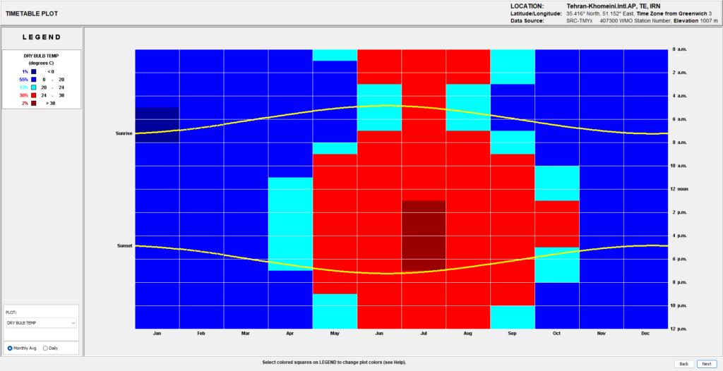
The bright red box indicates the time of every month when the dry bulb temperature is more than desired. This is the overheated period (including the maroon boxes).
Step 2: Plotting the overheated period on the sun-path diagram
Strictly speaking, we should shade for all of the overheated period. But I understand this is the case only for my location. So for the sake of this example, I will only shade from April to September. And obviously, we only shade from sunset to sunrise.
The next step is to figure out where the sun is situated in the sky at overheated times. We do this with the sun-path diagram. A sun-path diagram tells us where the sun is in the sky at any time of the year. Let’s learn to do this with an example. (For this tutorial, I will assume you know how to read a sun-path diagram).
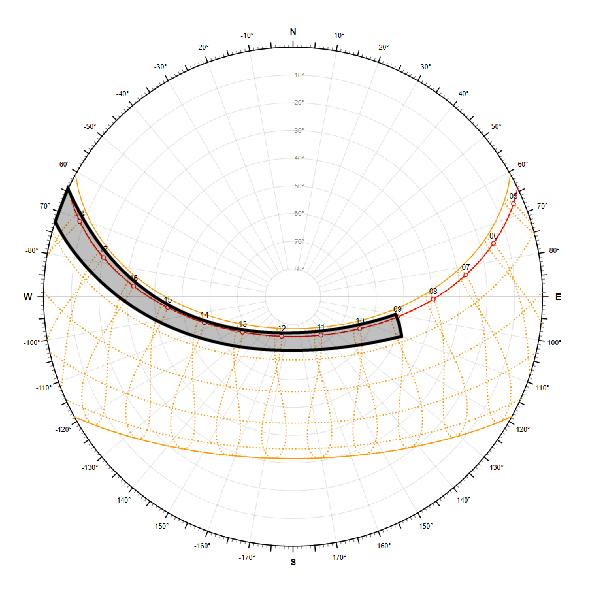
For May, the overheated period starts from 9 AM and continues till sunset. So let’s shade all the locations of the sun in May from 9 AM to sunset on the sun-path diagram. This is shown below as the shaded region.
Now we do this for all the months of the year. This is shown below as the shaded region.
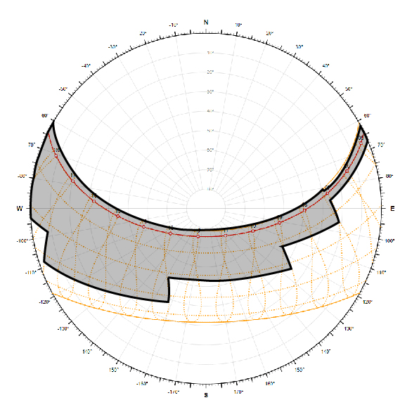
Now we know the sun’s location wherever it is too hot outside. Note that there will be times when the overheated and underheated hours coincide (it is not the case in this example). If that happens, shade the overheated hours and ignore the underheated ones.
Step 3: Figuring out the shading mask
It is impractical to shade for all the hours when the overheated hours either start from sunrise or go till sunset or both. This is because it results in an infinitely long shading device, at least theoretically. So we restrict ourselves to certain hours. For this example, I will restrict the shaded time to be between 8 AM to 4 PM. Now we need to figure out the shading mask.
A shading mask is a region marked on a sun-path diagram that shows the portion of the sky that will be obstructed when viewed through an opening from a pre-defined point of reference. Don’t worry if that reads too complicated. You’ll understand once we actually do it. Essentially, if we can’t see the sun, it means the sun’s rays won’t get inside the building, preventing it from overheating.
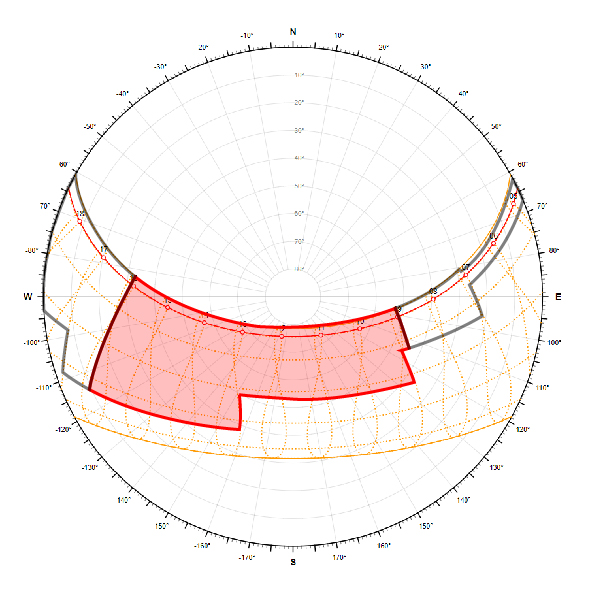
Once you have decided the hours for which you want to shade the opening, narrow down the overheated period to that much time on the sun-path diagram. You can see how I did it below. The red-shaded region is the shading mask.
Step 4: Finding out the VSA
Once we know when exactly we want to shade the opening and when the sun is located in the sky at those times, we break out the shading mask protractor or the solar protractor. For clarity’s sake, the curving lines in the protractor determine the VSA, the radial lines determine the HSA and the half-curving and half-concentric lines determine the EPA.
First, we need to know the orientation of the opening. I have shown the opening symbolically in the image. However, this is not necessary. After you have this down, overlay the shading mask on top of the protractor. If you are using overlay sheets, make sure the protractor and the sun-path diagram are of the same size. Otherwise, the shading mask will be out of proportion.
Orient the protractor so that the half used for calculating the VSA always points in the same direction as the opening. Do not move the shading mask’s orientation. To make this clear, I’ve given multiple orientations of an opening and how to arrange the protractor accordingly. We will proceed with the south orientation.
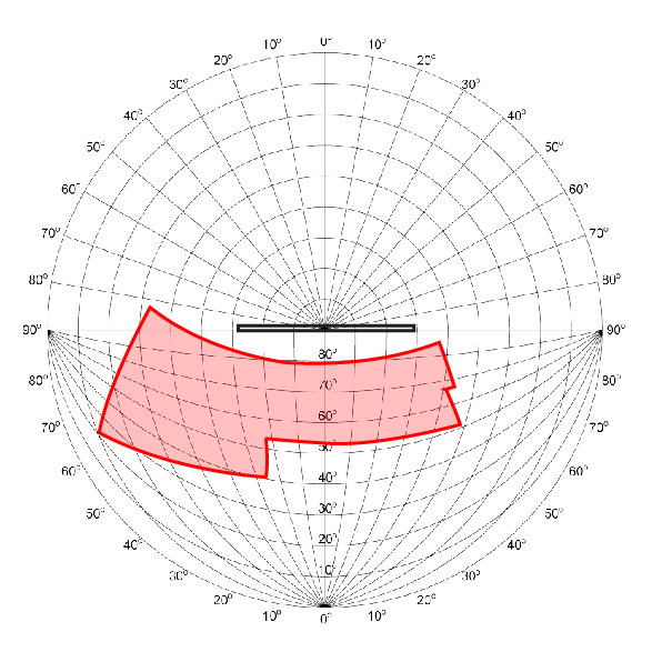
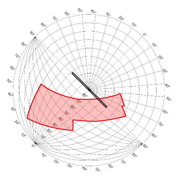
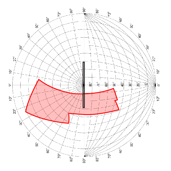
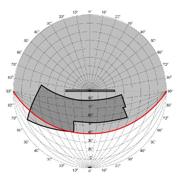
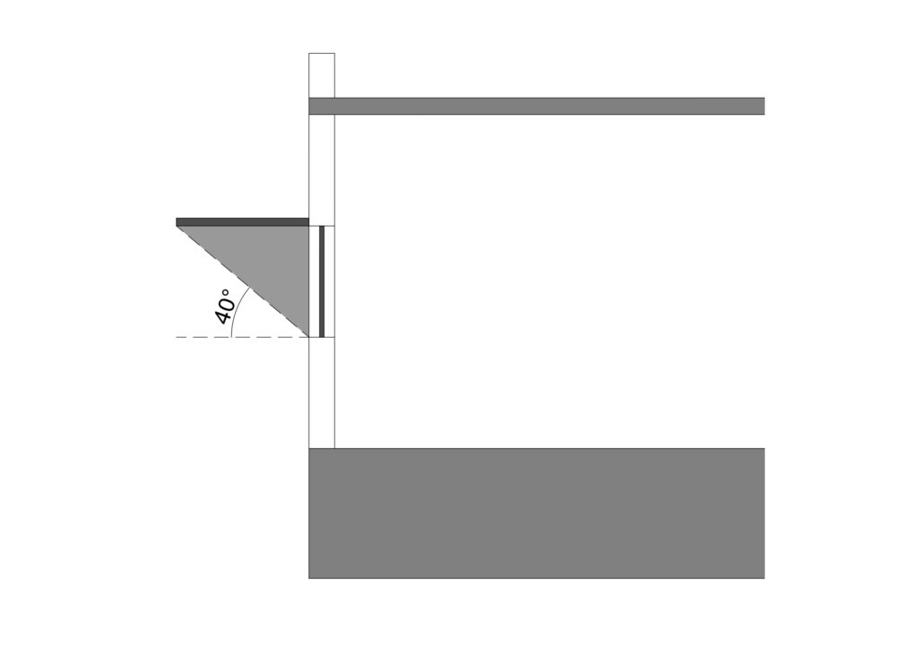
Choose the curving line that covers as much of the shading mask as is practical. I have chosen the 40o line. This is shown in red below.
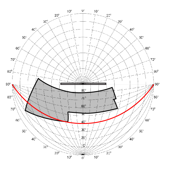
This means whenever the sun’s altitude angle is greater than 40o, the overhang will block it. Graphically, this is represented as below.
Step 5: Finding out the HSA
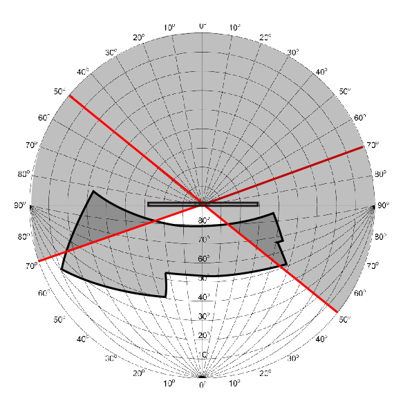
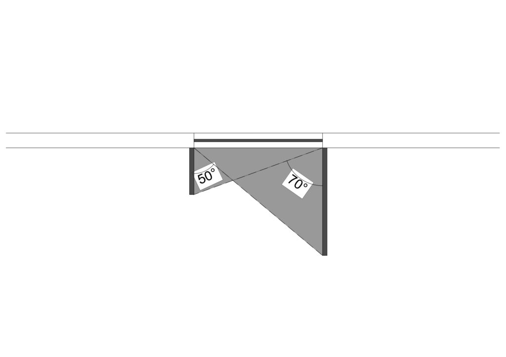
Now for the HSA. Extend a radial line in the upper half of the protractor so that it becomes like the diameter of the protractor. This radial line should cover as much of the shading mask as is practical. I have chosen a 70o line on the west side and a 50o line on the east side. These are shown in red and blue respectively below.
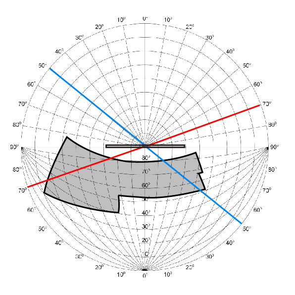
This means whenever the sun’s azimuth angle is greater than 70o measured from due south clockwise, the vertical fin on the west side will obstruct it. Whenever the sun’s azimuth angle is greater than 50o measured from due south counter-clockwise, the vertical fin on the east side will obstruct it. This is shown below.
Step 6: Finding out the EPA
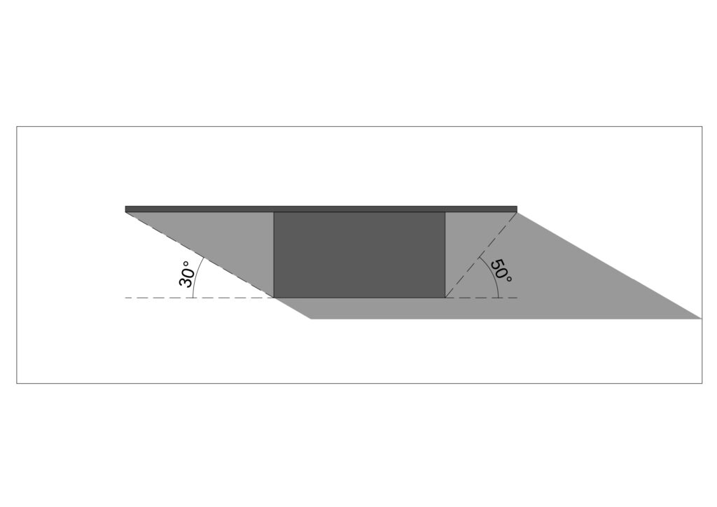
For the EPA, choose a suitable EPA line on the protractor such that it covers a maximum of the shading mask without being impractical. I have chosen an angle of 30o for the west side and an angle of 50o for the east side. Red and blue lines respectively show this below.
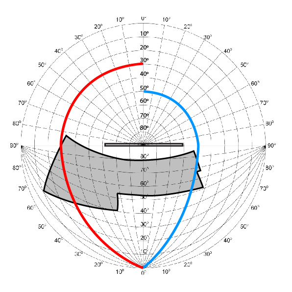
So now we have found out the VSA, HSA, and the EPA.
- VSA = 40o
- HSA = 70o (west) and 50o (east)
- EPA = 30o (west) and 50o (east)
Here is an opening with the VSA, HSA, and EPA as specified above.
The truth about solar shading devices
While an effective passive strategy for lowering solar radiation entering the building, an immovable shading device, be it an overhang or a vertical fin, has definite disadvantages. The biggest one is that they are attuned to the sun’s path in the sky and not to the actual heat entering the atmosphere. Let me explain.
The mass of the earth is very great. Hence, it takes a lot of time for it to heat up. So even though the sun is farthest from the earth on December 21 (winter solstice), the coldest months are in January and February. This is because the actual temperature in the atmosphere lags behind the sun’s trajectory by one to two months. But if we design a solar shading device based on the method explained above, the shading will be least in December and start increasing in January and February, months when we do need the sun’s rays to enter the building.
The answer to this is simple. Movable shading devices. These are not expensive and with minimal adjustments, as little as two times a year, a much more effective shading strategy can be devised.
However, actually ‘designing’ a shading device is much better than constructing a ‘standard’ length device. So this method is very much worth learning.
Let me know if you all have any questions in the comments below.


